¶ Firewall exceptions
For CredoID to be able to Discover and communicate with controllers - firewall inbound rule must be created.
¶ Default ports used by devices
- HID VertX: 4070, 4050 TCP
- HID Aero: 3002 TCP
- Mercury: 3001 TCP
- CredoID web client: 8090 TCP
- CredoID Checkpoint mobile application: 58032 TCP
- ASB Security: 20002, 20005 TCP
- FATH Mechatronics TANlock3 : 2001, 2002 TCP
Default ports can be changed in additional-settings.
¶ How to create Windows firewall inbound rule
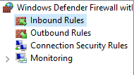
To create a firewall inbound rule - open Windows Defender Firewall with Advanced Security.

- Click Inbound Rules.
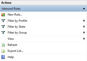
- On the right side of window in Actions section click New Rule….
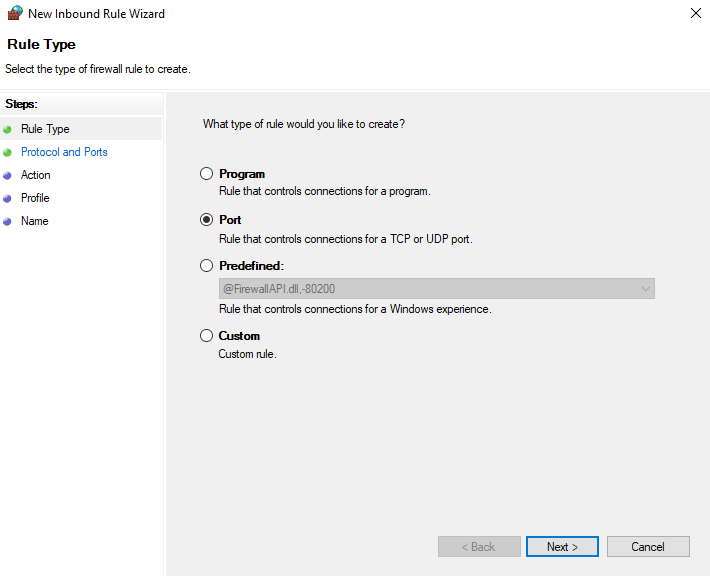
- Select Rule Type - Port and click Next.
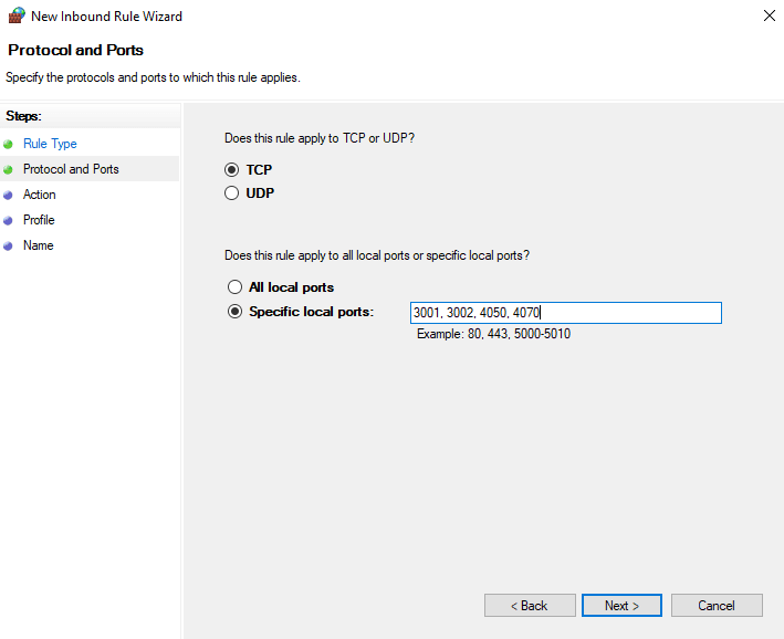
- Select Protocol - TCP and Specific local ports: 3001, 3002, 4050, 4070 (Mercury, Aero and VertX) and click Next.
- Select Action - Allow the connection and click Next.
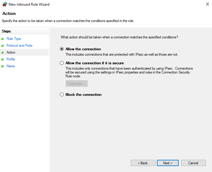
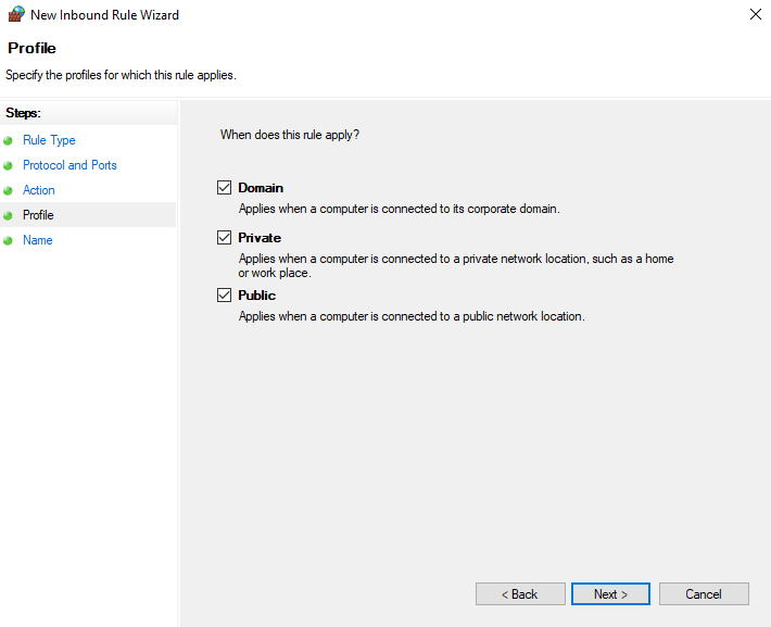
- Select which network profiles this rule will be applied to and click Next.
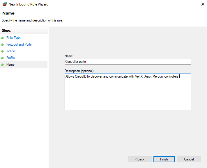
- Enter name of the Inbound Rule and click Finish.
¶ Admin password reset
Service has to be stopped before resetting password.
To stop the service - open "Task manager", navigate to "Services", find "CredoID Service", right click on it and select "Stop".
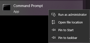
Click start, type cmd, right click on "Command Prompt" and select "Run as administrator".
Navigate to "C:\Program Files\Midpoint-Security\CredoID\Service" in Command Prompt by typing:
cd C:\Program Files\Midpoint-Security\CredoID\Service
Then type:
MDP.SID.Launcher.exe /AdminPasswordReset=true
It will start the service with default admin:admin password.
After service has initialized with default password - you can close "Command prompt" and resume service via task manager.
¶ ASB Musdo Security PSTN Module
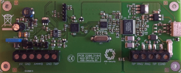
This expander can be used to transmit PSTN alarm messages to the alarm receiver center.
Only 1 CCS3800 Mbus PSTN module can be placed on the CCS7000/5000 system.
¶ Connection
¶ MBus
4-wire connection on Mbus. Daisy chain setup.
The Mbus is connected to the connection terminals +Vin, GND, A and B.
¶ Tamper
TMP connection can be used to connect the tamper switch. This input is configured as NC(Normally closed).
¶ Phone Line
In on-premises wiring the first or only pair of inside wiring and jacks are color-coded in green for the tip conductor, and red for the ring side.
¶ I/O Linker rules for VertX devices
Used in CredoID v4, placed in Devices → Select device → IOLinkers.
¶ I/O Linker Rules
Purpose: Defines rules which link output action or event messages to a Boolean expression composed of physical, schedule, or logical inputs.
Structure: Each rule is composed of three parts: a Left-Hand Side (LHS) expression, a Boolean operator, and a Right-Hand Side (RHS) expression.
Sample Listing
# IO Linker Rules configuration file
# O(IF,nn) - Output (set/clear type)
#
# = I(IF,ii)
# = L(logid) - Logical Bit
#
# where IF = interface board (IF=32 for Local IO)
# nn = function code
# ii = input status bit
¶ Interface units reference table
| VertX V100 | nn | VertX v200 | ii | VertX v300 | nn |
|---|---|---|---|---|---|
| Aux Relay | 1 | Relay #1 | 0 (nn) | Relay # 1 | 0 |
| Aux 2 Relay | 17 | Relay #2 | 1 (nn) | Relay # 2 | 1 |
| Door 1 - Door Switch | 12 (ii) | Input 1 | 16 | Relay # 3 | 2 |
| Door 2 - Door Switch | 14 (ii) | Input 2 | 18 | Relay # 4 | 3 |
| Input 3 | 20 | Relay # 5 | 4 | ||
| Input 4 | 22 | Relay # 6 | 5 | ||
| Input 5 | 24 | Relay # 7 | 6 | ||
| Input 6 | 26 | Relay # 8 | 7 | ||
| Input 7 | 28 | Relay # 9 | 8 | ||
| Input 8 | 30 | Relay # 10 | 9 | ||
| Input 9 | 32 | Relay # 11 | 10 | ||
| Input 10 | 34 | Relay # 12 | 11 | ||
| Input 11 | 36 | Input Point 1 | 0 (ii) | ||
| Input 12 | 38 | Input Point 2 | 1 (ii) | ||
| Input 13 | 40 | ||||
| Input 14 | 42 | ||||
| Input 15 | 44 | ||||
| Input 16 | 46 |
¶ Examples
Set initial output state during a start or a cold restart:
SET L(1) FALSE
Turn on Aux relay 1 on V100 (module IF=14) when the doors are open (door switch 1) on reader 1:
O(14,1) = L(1) | I(14,12)
Turn on Aux relay 2 on V100 (module IF=14) when the doors are open (door switch 2) on reader 2:
O(14,17) = L(1) | I(14,14)
Turn on Relay #5 on v300 (module IF=4) when input 5 is triggered on v200 (module IF=2):
O(4,4) = L(1) | I(2,24)
Turn on Relay #1 on v200 (module IF=6) when input 12 is triggered on v200 (module IF=6):
O(6,0) = L(1) | I(6,38)
Turn on Relay #9 on v300 (module IF=3) when input 2 is triggered on v300 (module IF=3):
O(3,8) = L(1) | I(3,2)
¶ Open Supervised Device Protocol (OSDP)
OSDP is an access control communications standard developed by the Security Industry Association (SIA) to improve interoperability among access control and security products.
OSDP describes the communication protocol for interfacing one or more readers to a controller. The OSDP specification describes the protocol implementation over a two-wire RS-485 multi-drop serial communication channel. Nevertheless, this protocol can be used to transfer secure data over any physical channel.
OSDP enables bi-directional communication between reader and controller. Refer to your controller documentation for required configuration.
¶ Secure channel
Secure Channel is the encryption and authentication scheme used by OSDP V2 compliant devices to protect communication between controllers and readers. Secure Channel creates a secure session by using various initialization messages, which perform mutual authentication and establish a set of keys that are used in controller to reader communication.
Enabling secure channel disables install mode.
¶ Setting up readers to use secure channel
To set up HID Readers you need to have "HID Reader Manager" mobile application or a configuration card.
To use secure channel - reader should use OSDP and has to be in install mode before full synchronization with controller. To set up reader through "HID Reader Manager" application:
- Open "HID Reader Manager".
- Press "Scan for readers".
- Select your reader.
- Press "Inspect reader".
- Press "Detailed configuration".
- Press "Communication protocol".
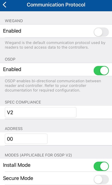
- Enable OSDP and Install mode.
- Scroll down to the bottom of menu, press "Add to the template".
- Press "Apply Selected Items".
Some readers may require to cycle power after step 5.
Communication protocol screen should look like this:
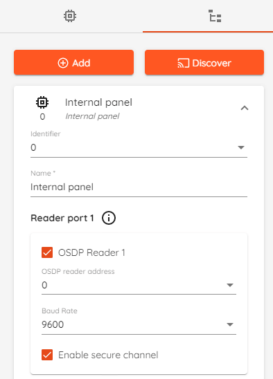
To enable secure channel in "CredoID":
- Go to device list which can be found in "Hardware" -> "Devices".
- Select device that your reader is connected to.
- Go to "Device modules" tab on the right side of the screen.
- Click on module that your reader is connected to.
- Scroll down to whatever port your reader is connected to, check mark "OSDP" and "Enable secure channel".
- Check if OSDP reader address and Baud Rate is correct.
- Click "Save".
- Synchronize your controller.
¶ Secure Channel Session
A Secure Channel session is initiated with a handshake that involves 2 command-reply transactions between the controller and reader. A session once established can be kept active endlessly until either party decides to discard it or until a timeout occurs.
¶ Reader modes
In install mode the default secure channel key can be used.
In secure mode, only commands sent over secure channel are accepted.
Modes are only applicable for OSDP V2.
¶ Sync error issue with controllers
This might happen when updating CredoID from older version to newer one. After update, launch CredoID, wait until devices come online. If they come back in state "Sync error", select all and "Synchronize". Devices will come back in "Completed" state after few minutes.
¶ CredoID Docker container
You can obtain the latest build of CredoID Docker container from Docker hub:
https://hub.docker.com/r/midpointdev/credoid
Docker Pull Command: docker pull midpointdev/credoid
For license please contact Midpoint Security support or order one through our partner network.
¶ Duress PIN
A duress code is a covert distress signal used by an individual who is being coerced by one or more hostile persons. It is used to warn others that they are being forced to do something against their will.
CredoID has a Duress PIN feature - if duress pin is used, access is granted as it would normally be, but event with reason „Duress code used“ is generated which can be used to trigger certain actions.
Duress pin code support is currently always enabled without any additional configuration. The default behavior functions only when the reader is in the „Card & PIN“ mode.
To use „Duress PIN“ with „CredoID“ - when entering pin you just have to add 1 to the last digit of your pin, for example if your pin is "1234" you'll have to enter "1235", if it ends with „9“ switch it to „0“.
„Duress PIN“ feature is implemented in „CredoID“ since version 4.10.221
¶ Migration tool
Migration is possible only from CredoID v.4.11.288.
If you are running Microsft SQL, you have to update current version to 4.11.288 and run migration tool. Database will be converted to PostgreSQL. Install 4.12.0 and run it on converted PostgreSQL database.
This tool is used to migrate database from Microsoft SQL Server to a PostgreSQL Server.
CredoID supports PostgreSQL version 14.0 and above
It is also possible to order migration service from us, let us know by e-mail sales@midpoint-security.com
¶ Preparation for migration
Before migrating:
- CredoID has to be updated to v4.11.288.
- PostgreSQL DB has to be installed.
It's best to install PostgreSQL database from embedded installer in CredoID setup.
Another option is official standalone installer from PostgreSQL website .
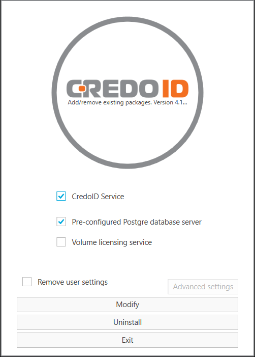
To install PostgreSQL DB if you already have CredoID v4.11.288 installed - run CredoID setup again and select "Pre-configured Postgre database server" and click "Modify".
PostgreSQL installation.
¶ Migration process
Download migration tool from CredoID repository. Current tool version is migration-tool-1.0.28.
After downloading and extracting the contents:
- Open "Migration tool" folder.
- Open "appsettings.json" file with any text editor.
- Find "SourceDatabase" and "DestinationDatabase" in .json file, both of them has "ConnectionString" parameters.
  "SourceDatabase": {
    "ConnectionString": "Server=.\\SQLEXPRESS;Database=CredoID_MSSQL;User Id=sa;Password=CredoIDPassword1; MultipleActiveResultSets=true;"
  },
  "DestinationDatabase": {
    "ConnectionString": "Server=localhost;Database=CredoID_PG;User Id=postgres;Password=CredoIDPassword1;"
  },
Connection string parameters for "SourceDatabase" can be copied from your current "config.json" file which is located in "C:\ProgramData\Midpoint-Security\CredoID Service"
"MultipleActiveResultSets=true;" is a required parameter for source database "Connection String", you might need to remove it from "config.json" file after migration.
- Edit connection details for the source SQL Server.
- Edit connection details for the destination PostgreSQL Server.
- Run MDP.SID.Database.Migration.Tool.exe.

- Update and run CredoID after migration is done, you should be presented with "Database setup" page.
If you get "The given key was not present in the dictionary." message - you will need to remove "MultipleActiveResultSets= true;" from "config.json" in "C:\ProgramData\Midpoint-Security\CredoID Service".
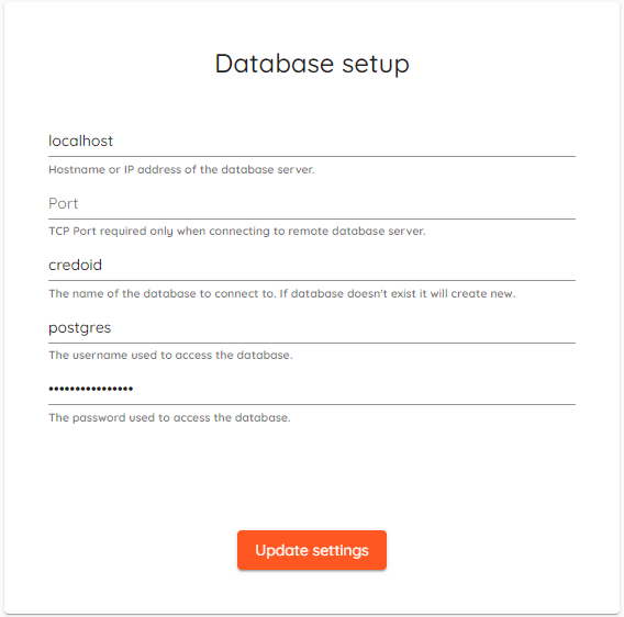
- Enter your "PostgreSQL" database details and click "Update settings".
NOTE: Please check the destination database for errors. Don't forget to fully synchronize devices.
¶ MR-50-S3B Jumper J602
The MR-50-S3B introduces a new jumper next to the reader port labeled J602. This is a 120Ø termination jumper used for OSDP connections.
If using a non-OSDP reader this jumper should be open.
If using OSDP, then this jumper should be terminated.
¶ Remove WRN logs from Windows Event viewer
To remove event log messages from being logged in Windows Event viewer add config section below to "C:\ProgramData\Midpoint-Security\CredoID Service\config.log.json" :
 "Logging": {
    "EventLog": {
      "LogLevel": {
        "Default": "None"
      }
    }
  }
¶ Aperio AH40 IP Hub offline after migrating to 2.0+
When using an AH40 Aperio IP Communication hub and communicating using TLS, the device will be offline after a firmware migration from 1.x to 2.x due to a mismatch of certificates. To resolve, the following steps must be taken:
- Within the web UI of controller, select Certificate Manager.
- Generate a new certificate for Aperio use. The values entered during the creation do not impact functionality, however, aside from password field, do not leave entries blank.
- Set certificate to expire to the maximum allowed value.
- Apply Settings and Reboot controller.
- Within Aperio application, set hub to manufacturer mode - only in this mode will the hub accept a new certificate.
- The hub should then be able to come online and communicate to the controller.
- Within Aperio application, set hub to customer mode - preventing hub from accepting any new certificates.
¶ Reset database Password For postgres User
For some reason, after installing PostgreSQL, you may forget the password of the postgres user. In such cases, you need to know how to reset the password to regain access to the PostgreSQL server.
PostgreSQL uses the pg_hba.conf configuration file stored in the database data directory (e.g., C:\Program Files\PostgreSQL\16\data on Windows) to control the client authentication. The hba in pg_hba.conf means host-based authentication.
To reset the password for the postgres user, you need to follow these steps:
- First, modify some parameters in the
pg_hba.confconfiguration file. - Log in to the PostgreSQL server using the
postgresuser account without a password. - Reset the password.
The following steps show you how to reset a password for the postgres user:
-
Backup the
pg_hba.conffile by copying it to a different location or rename it topg_hba.conf.bk -
Edit the
pg_dba.conffile and change all local connections fromscram-sha-256totrust. By doing this, you can log in to the PostgreSQL database server without using a password.
# TYPE  DATABASE        USER            ADDRESS                 METHOD

# IPv4 local connections:
host    all             all             127.0.0.1/32            trust
# IPv6 local connections:
host    all             all             ::1/128                 trust
# Allow replication connections from localhost, by a user with the
# replication privilege.
host    replication     all             127.0.0.1/32            trust
host    replication     all             ::1/128                 trust
- Restart the PostgreSQL server. If you are on Windows, you can restart the PostgreSQL from Services.
Alternatively, you can run the following command from the Command Prompt (notice that you need to run the Command Prompt as the Administrator):
pg_ctl -D "C:\Program Files\PostgreSQL\16\data" restart
The "C:\Program Files\PostgreSQL\16\data" is the data directory.
- Connect to PostgreSQL database server using any tool such as psql or pgAdmin:
psql -U postgres
PostgreSQL will not require a password to log in.
- Execute the following command to set a new password for the
postgresuser.
postgres=# ALTER USER postgres WITH PASSWORD 'new_password';
- Restore the
pg_dba.conffile, restart the PostgreSQL database server, and connect to the PostgreSQL database server with the new password.
Original source - Reset Forgotten Password For postgres User.
¶ Using HID Omnikey to enroll user credentials
HID Omnikey is a USB desktop reader. To use it with CredoID for credential enrollment - reader operation mode must be set to “Keyboard wedge” (KBW) - to set OMNIKEY readers' mode to Keyboard Wedge we recommend using “OMNIKEY workbench tool”.
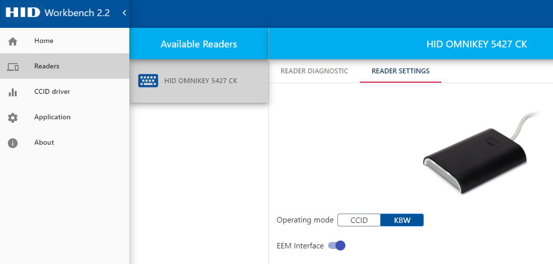
If reader is set to KBW mode and connected to the PC when entering credentials in CredoID - select "Card data" field, present a card to the reader and card data will be entered into the selected field.
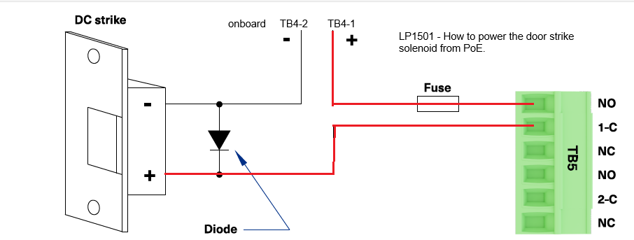
¶ How to power a door strike from POE+ using dry contact relay
¶ Updating Aero/Mercury firmware (1.31.x -> 2.x)
Before updating to 2.x make sure your controller it at least on v1.31.x FW, otherwise update to v1.31.x first.
Follow guide to Update FW via CredoID
or
- Navigate to controllers web UI, log in.
- Navigate to "Diagnostic" menu.
- Click "Choose File" and select firmware file.
- Click "Load File" and wait until the board reboots.
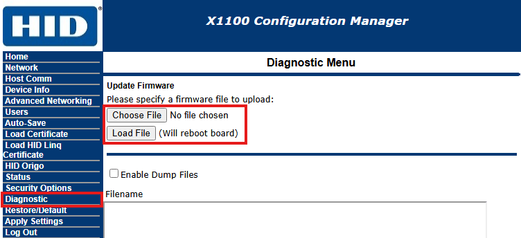
- The MIGRATION (1.31 to 2.x) takes roughly 20-50 minutes in total per controller (measured point-to-point over a LAN)
- The migration package will migrate 1.31.x controllers to the most recent version of 2.x.
- The 2.x migration package requires a minimum firmware version of 1.31.0.681.
- Migration to 2.0 is a one-way upgrade (1.31.x to 2.0+).
- A controller cannot be downgraded to 1.3 once on 2.0+.
- A controller synchronization is required after every firmware upgrade.